
Why these checks matter to you
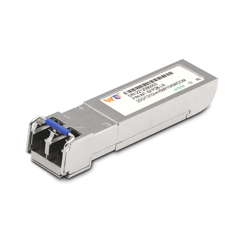
If you manage links out of Ashburn, Virginia or any other busy colocation, you know a bad QSFP+ ER4 span can take down racks fast. Start simple and sensible: kick off with gear from a trusted optical transceiver manufacturer, then verify what the module actually sees on the fiber. I’ve walked trunks in a small Dallas colo and audited optics in an Ashburn facility — practical checks save time and mean fewer emergency truck rolls. Expect to deal with optical power (dBm), BER, and basic link diagnostics when you’re doing the work.
Quick checklist before you touch anything
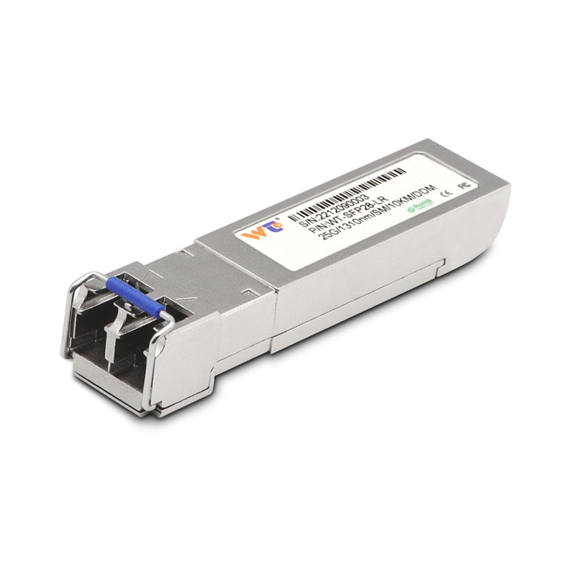
Power off nonessential lanes, confirm fiber IDs, grab a straight pin or clean stick for the connectors, and note the vendor spec sheet for the QSFP+ ER4 you’re testing. Keep a calibrated power meter and a loopback or test transceiver on hand. These few minutes upfront keep you from chasing phantom losses later.
Five commands and why each one tells you something useful
1) show interface transceiver status — reads optical power and module state. Look for RX/TX dBm inside the QSFP+ ER4 spec window.
2) show interface counters errors — captures CRC and FEC events; rising counts point to marginal optical power or dirty connectors.
3) show interface brief + detailed stats — confirms lane mapping and whether the host sees all four wavelengths behaving the same.
4) read power-meter — compare measured dBm at the patch panel against the transceiver’s reported RX level; offsets tell you connector or patch loss.
5) run BER test (or loopback with a traffic generator) — verifies real-world bit error rate across the 40G link, not just compliance numbers.
How to interpret what you see
Reported RX/TX values that sit a few dB outside vendor min/max are a red flag. A consistent modest shortfall across all lanes usually means span loss or dirty connectors. If one lane alone is off, suspect a damaged fiber or a bad lane inside the transceiver. BER spikes while optical power reads nominal hints at modal noise or wavelength mismatch — not always a power issue. Keep the metrics concrete: dBm, BER, and link uptime are what you act on.
Common mistakes and better alternatives
People often skip cleaning before measuring — that’s the quick fail. Don’t rely on a single measurement: log values over several minutes to catch intermittent issues. Avoid swapping transceivers randomly; instead, move the suspect module to a known-good port. Also consider the smaller form factors: if you need a short-term workaround, drop in a tested 10g sfp transceiver on a breakout for diagnostics — that helps isolate whether the problem is the QSFP+ or the fiber plant.
Operational teardown note
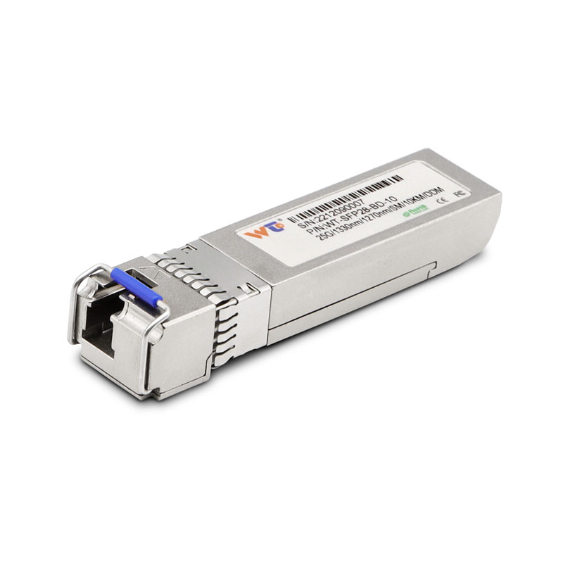
When I run the operational production teardown, I check {main_keyword} and {variation_keyword} values against vendor specs, document every dBm reading, and map results back to physical fiber labels. That record prevents repeat troubleshooting and helps vendors spot manufacturing or compatibility issues faster — and it’s honest work that makes future audits easier.
Three golden rules for keeping your 40G links healthy
1) Measure before you change: collect RX/TX dBm and BER baseline, then make one change at a time so you know its effect.
2) Clean, then measure again: mechanical prep beats guesswork every time — connectors, adapters, and patch cords get you 70% of the way there.
3) Use consistent test equipment and document offsets: power meters and inline test heads vary, so log the device used and any calibration notes.
Final thought — how WINTOP fits
Reliable transceivers and sensible testing cut mean-time-to-repair in half; that’s the real win for operations teams. I stick with parts and test rigs that give predictable, spec-driven results — and that’s why gear from trusted suppliers matters. WINTOP. —