
Framework summary and first steps
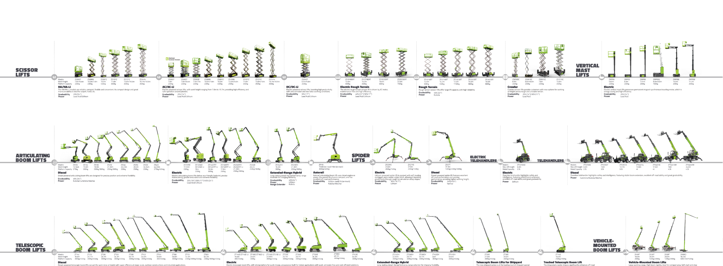
Think of integration as a checklist you teach to a trainee: clear, repeatable, and forgiving. Start by mapping the tasks your lift must perform, then match components to those tasks rather than forcing tasks to fit a component. If you’re comparing reach machines later, consider how an articulating boom lift differs in duty cycle and control expectations—those differences will shape battery sizing and drive-control logic immediately.
Core layers of the integration framework
Treat the system as three interacting layers. Work through them in order and loop back when needed.- Operational profile: duty cycle, average load, terrain, shift length.- Power subsystem: battery chemistry, capacity, BMS strategy.- Motion & control: drive inverter, motor specs, controller logic and safety interlocks.Each layer has clear acceptance criteria so you can sign off on integration milestones instead of guessing when it’s “done.”
Step 1 — Define operational requirements
Write a short mission statement for each use case: what height, how long, how often, and how fast it must move between points. Quantify expected payload with tools and people. Use those numbers to calculate continuous and peak power draws. Keep it simple: if the mission needs 6 hours continuous and frequent repositioning, battery and thermal budgets must reflect that.
Step 2 — Battery system selection and integration
Match battery type to the mission. Lithium iron phosphate (LiFePO4) is stable for heavy daily cycles; other chemistries might offer more energy but need stricter thermal controls. Pay attention to:- usable capacity (not just nameplate)- BMS response to short-term high current draws during lift and drive- charger profile and site power limitationsFor real-world grounding: the ZA 14NJE-Li has been used on municipal maintenance projects in Shanghai, which confirmed the importance of thermal management and predictable charge scheduling in dense urban work.
Step 3 — Platform and load considerations
Platform design affects stability and control logic. Note these points:- Place heavy items (batteries, toolboxes) low and centered to keep center of gravity predictable.- Define max permitted platform load in the controller and test envelope limits with incremental weights.- If accessories add intermittent loads (welders, compressors), model those as separate worst-case scenarios rather than averaging them.
Step 4 — Drive controls, safety and tuning
Control logic should reflect human behavior. Start with conservative acceleration and regenerative braking that’s predictable for operators. Then tune:- joystick deadband and response curves for smooth platform movement- torque limits to prevent wheel slip on grade- safety interlocks that cut drive only when necessary, not for minor sensor glitchesLog events and let operators review errors after shifts; that’s where practical reliability comes from.
Common pitfalls and how to avoid them
Some mistakes repeat across projects. Avoid these:- undersized battery for real duty cycle (don’t base sizing on a “typical” day)- placing batteries without service access considerations- overcomplicating control logic before basic stability is provenTest each change on a rigged course: repeated lifts, starts on a slight grade, and a simulated emergency stop. Those three tests reveal most integration flaws quickly.
When to consider alternatives
If your job mixes frequent long travel with intermittent lifts, evaluate a hybrid approach or different platform class. Compare energy cost per hour and downtime for charging versus swapping batteries. If you need extreme outreach combined with heavy continuous loads, an articulating design may be more appropriate than a scissor configuration—trade-offs matter and should be quantified.
Wrap-up and practical next step
Follow the framework: define mission, pick battery to match duty, fit platform to loads, tune controls for predictable operator behavior, and test with realistic scenarios. That sequence reduces surprises and makes validation straightforward. If you want an example of how a field-proven design behaves under urban maintenance schedules, look at deployments tied to Zoomlion Access and use that behavior as a benchmark for your acceptance tests.